Beijing Phoenix TV&News Center Office Building
Beijing Phoenix TV&News
Beijing Phoenix TV&News Center Office Building
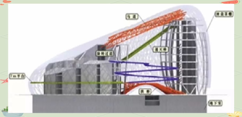
-Arch Canpies,circular ramps,sky ladders, arch bridges, platforms, and horse paths
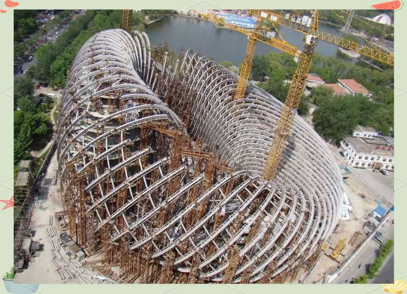
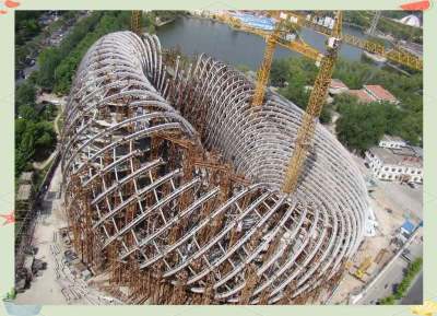
Beijing Phoenix Center, as the new media headquarters of Phoenix Group in Beijing, is not only a comprehensive building that integrates television program production, office, and commercial functions but also carries numerous innovations in technology and art. The project was carefully designed by the BIAD_UFo studio, led by Shao Weiping, and took over six years from the start of design in June 2007 to completion in July 2013. It covers an area of approximately 1.88 hectares, with a total construction area of 72,478 square meters and a building height of 54 meters, showcasing a perfect blend of grandeur and modernity.
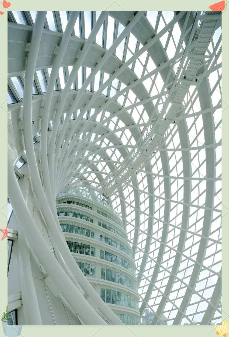
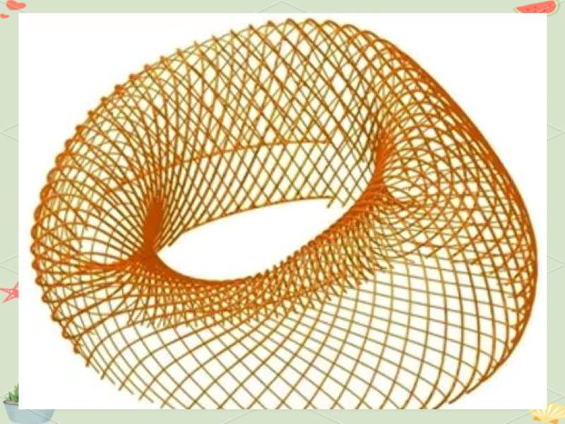
By cleverly utilizing the design concept of the Möbius strip, the high-rise office area and media studio harmoniously integrate, providing a comprehensive program production venue and supporting service facilities while creating a smooth and dynamic spatial volume. Its unique architectural form beautifully complements the natural landscape of Chaoyang Park, forming a picturesque tapestry of harmonious coexistence between humanity and nature. Meanwhile, the ingenious application of parametric and digital construction technologies made the design and construction process of the entire project appear effortless, fully demonstrating the remarkable achievements of contemporary steel structure technology.
Gao Jiling, as the Deputy General Manager, Chief Engineer, and Senior Engineer Researcher of ZHM Huawu Steel Structure, not only possesses a profound industry background and academic accomplishments but is also the overall leader for the deepening design and manufacturing of the steel structure for the Phoenix Center. In an exclusive interview with AC "Architectural Creation" magazine, he shared many insights and reflections regarding the Phoenix Center project. When discussing the "Phoenix Center" project, Gao Jiling particularly emphasized the four major technical challenges in the deepening detailing design and manufacturing of the steel structure: the deepening detailing design technology for the transmission of three-dimensional architectural form information, the processing technology for primary and secondary ribs, the processing technology for steel arch bridges, and the installation technology for steel structures. The successful application of these technologies not only highlights China's excellence and innovative capability in the field of steel structure manufacturing but also provides valuable experience and inspiration for future architectural creations.
The first challenge faced is the massive information processing challenge brought by the three-dimensional complex architectural form. In this project, traditional paper-based two-dimensional construction drawings could no longer meet the needs for conveying design information. By the time we got involved, Chief Architect Shao Weiping had already begun constructing the CATIA model, and the steel structure framework had taken initial shape. Although the details still needed refinement, the overall framework laid the foundation for subsequent work. The key was how to convert the CATIA model into two-dimensional drawings. It is worth noting that the construction drawings provided by the structural professionals at that time (i.e., traditional two-dimensional construction drawings) were relatively brief; relying solely on these for processing design would make it difficult to achieve the required precision due to insufficient information contained in the drawings.
At the beginning of this project, our primary task was to develop a set of construction drawings to guide manufacturing and processing. However, faced with the challenge of how to use CATIA software for steel structure processing, we engaged in in-depth communication with the structural designers. After two discussions, we made two key decisions: first, the steel structure construction drawings would follow the traditional drawing method, mainly serving as a basis for program execution but not directly used for deepening design and manufacturing; second, to fully utilize the CATIA software model already constructed by Chief Architect Shao Weiping's team, we would closely collaborate with their team for the deepening design and manufacturing of the steel structure.
In subsequent operations, we gradually uncovered challenges in the application of the CATIA model. Due to our team's lack of professionals proficient in CATIA software, while Shao's team had software operational capabilities, they were largely unfamiliar with the technical conditions and requirements for steel structure processing. Although we attempted to combine the strengths of both parties by having the design team's CATIA operators input the necessary information for steel structure manufacturing into the model, practice proved this method unfeasible. The main reason was that the software operators lacked an understanding of the requirements for steel structures, making it difficult to accurately convey information; moreover, the details and volume of information involved in deepening design and manufacturing of steel structures were immense. If all were reflected in a single model, it would lead to excessively large model data that could not effectively operate within the software.
This experience aligns with our understanding within the BIM system: each discipline should establish its own model, while the overall integration model often needs to omit a large amount of detailed information. If there is too much detailed information, the overall model will become too large to be usable in practical operations. The same problem also appeared in our subsequent application in CATIA software.
Single Discipline Model of Steel Structure in Rhino Software
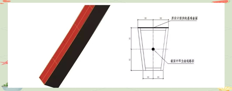
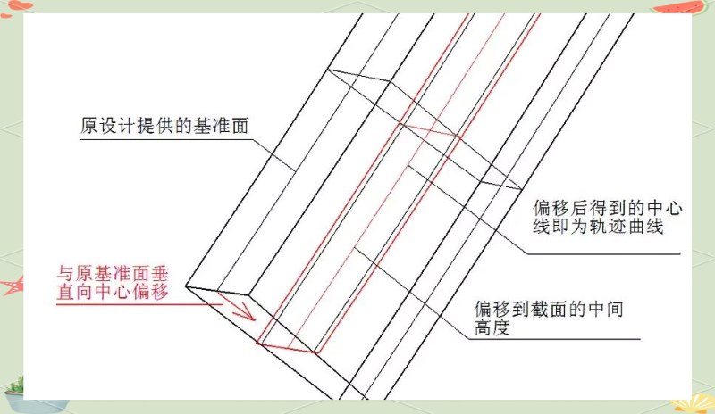
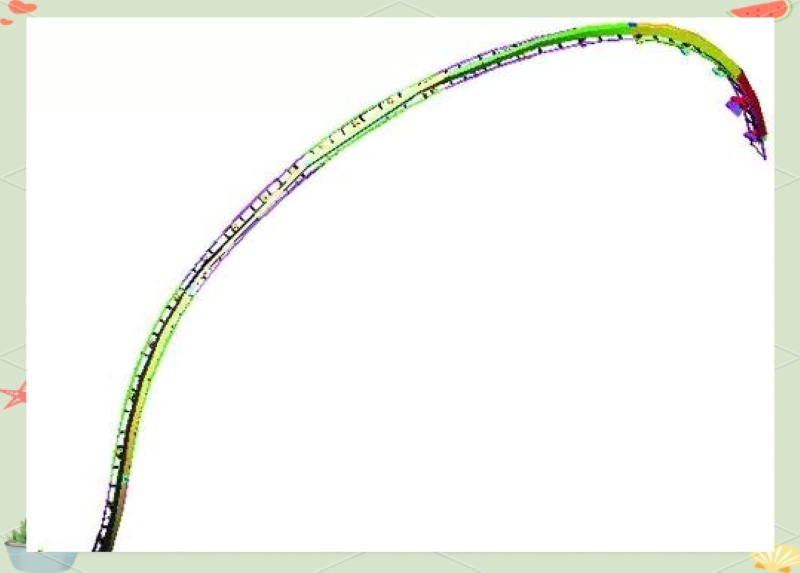
Method for Creating Trajectory Curves: We fitted the reference surface to generate trapezoidal cross-section trajectory curves that align with the original design line.
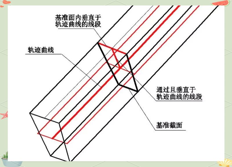
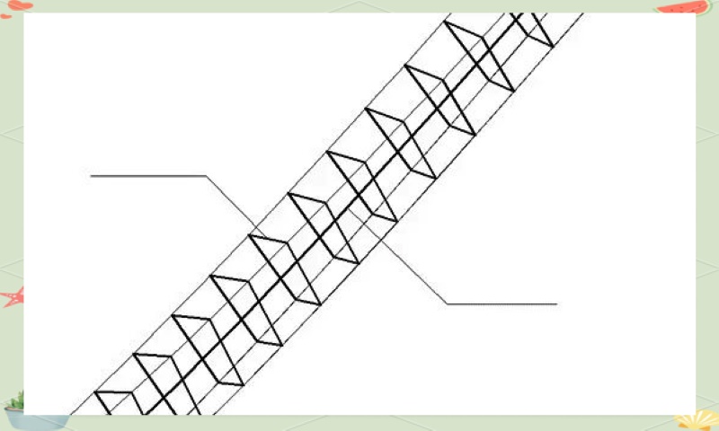
Arrangement of Reference Cross-sections for Twisted Components: Using the trajectory curve method, we fitted all reference surfaces to generate trapezoidal cross-section trajectory curves that align with the original design line.
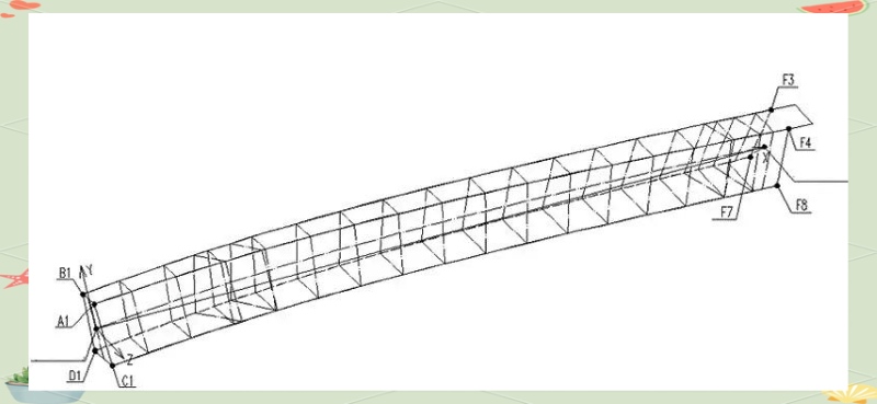
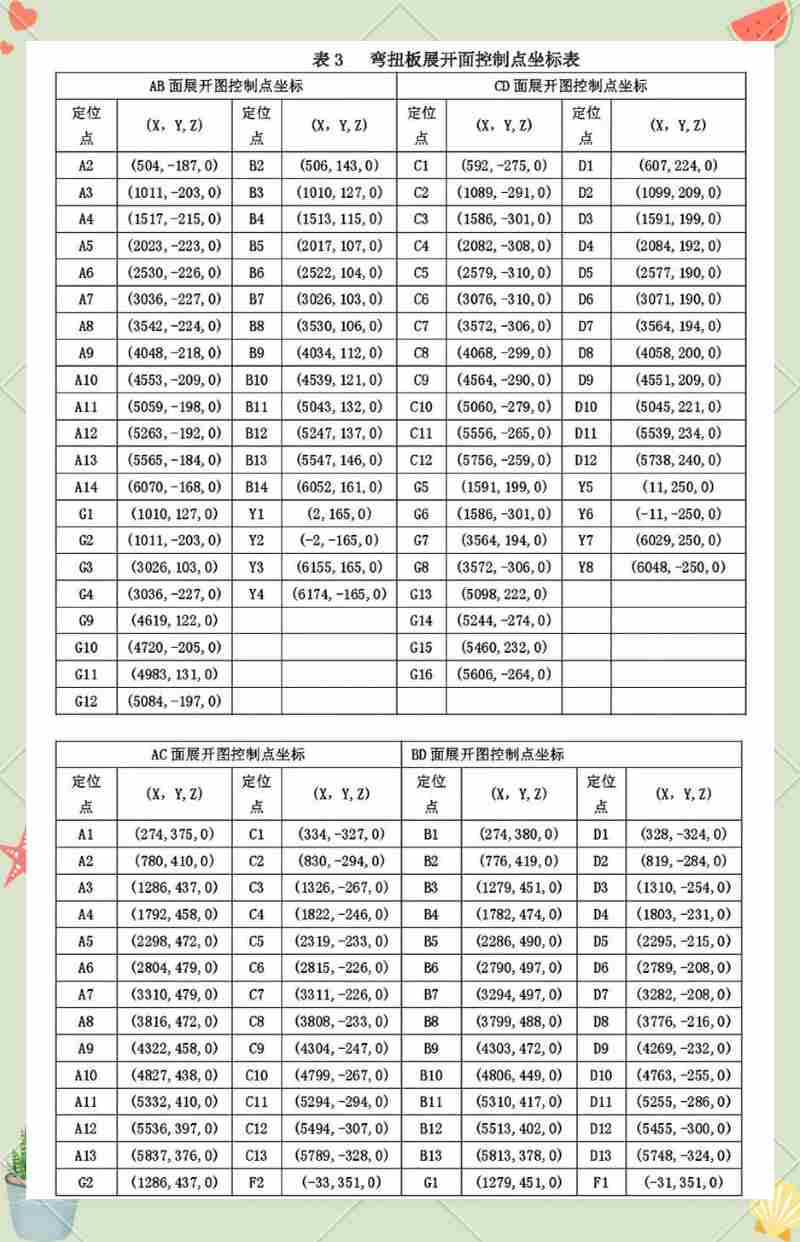
Based on the arrangement of reference cross-sections, we can further determine the numbering of positioning control points on each surface. This allows us to clearly grasp the bending and twisting states and positional information of each panel.
Through this approach, we successfully integrated the three steps of "precise expression of design intent - production processing layout - drawing of planar processing diagrams," achieving efficient and seamless transmission of architectural three-dimensional data. This innovative model not only improved design efficiency but also brought great convenience to production processing. Later, this model was widely applied in handling three-dimensional complex architectural components, such as the complex curved surface structures of Kunming Airport, where we easily solved processing challenges. We explored an effective way to transform the complex forms of architectural design concepts into concrete, manufacturable practical operations.
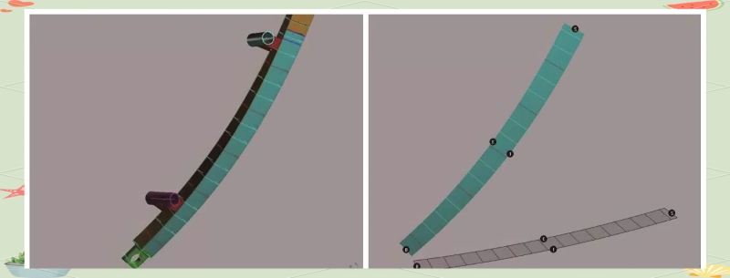
Spatial Unfolding of the Twisted Panel
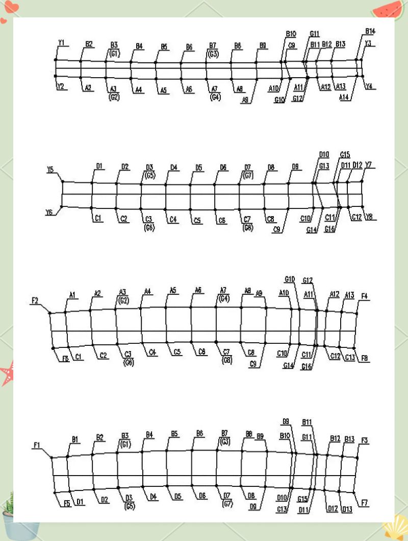
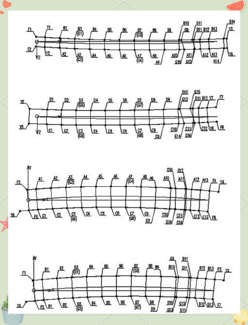
Control Point Numbering for the Unfolded Twisted Panel
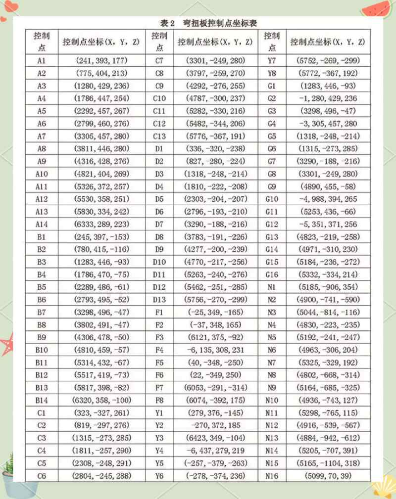
Coordinate Table of Control Points for the Unfolded Twisted Panel
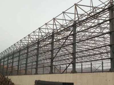
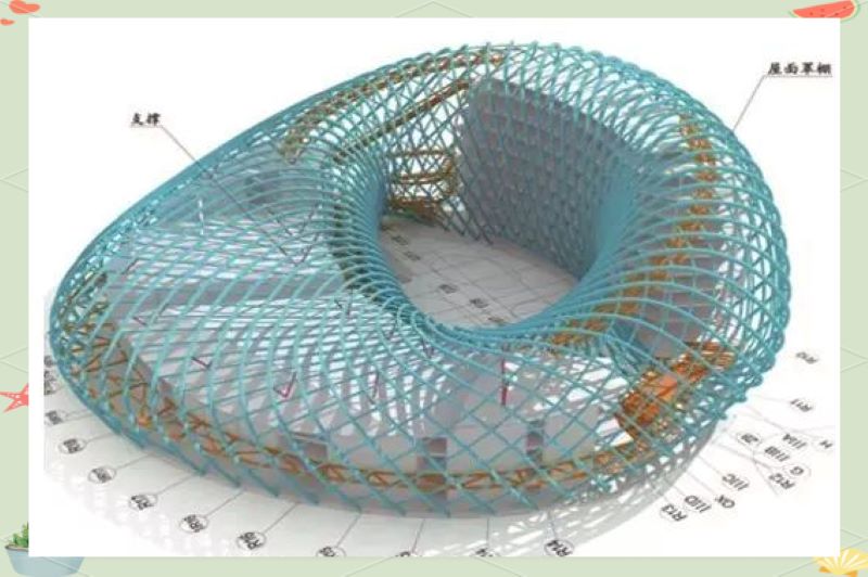
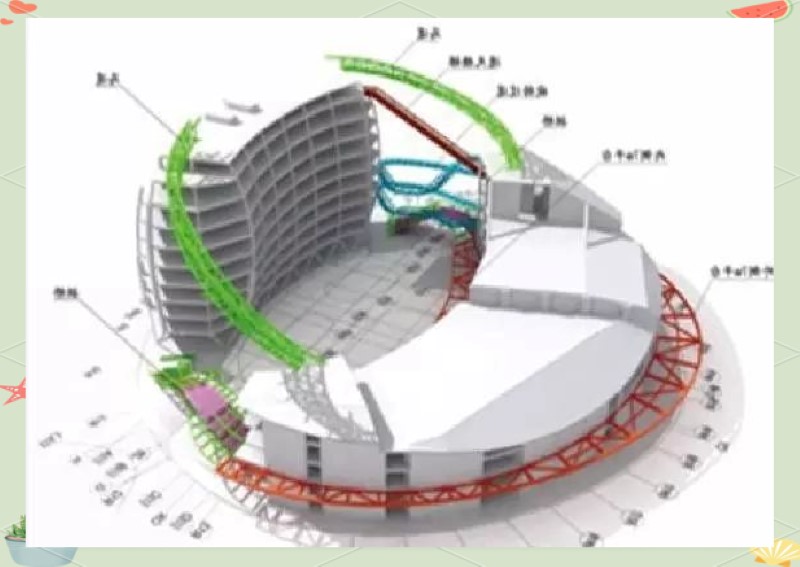
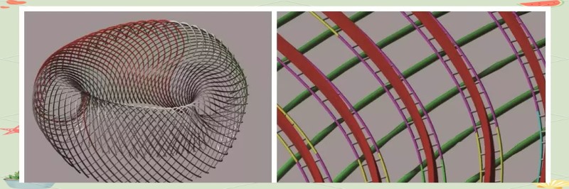
Steel Structure Canopy Design
Axonometric Analysis of a Single Twisted Main Ribs
Enlarged View of the Double-layer Diagonal Circular Frame
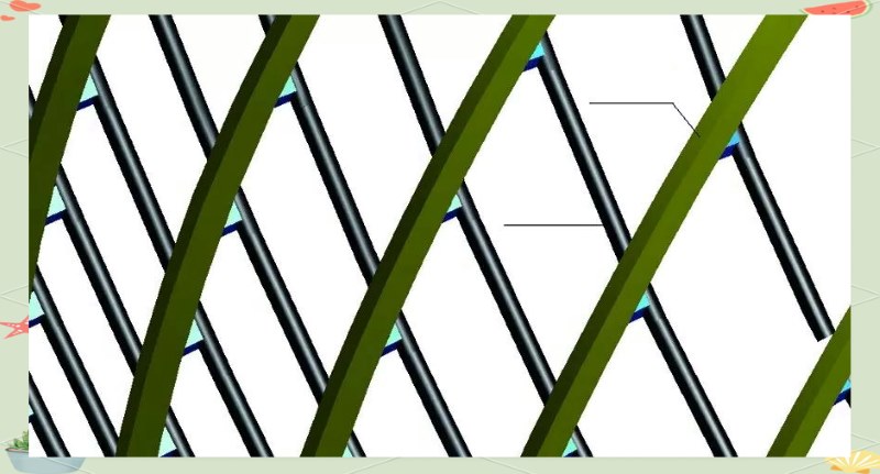
Axonometric View of the Connection Between the Twisted Main Ribs and Secondary Ribs
Composition of Twisted Main and Secondary Ribs
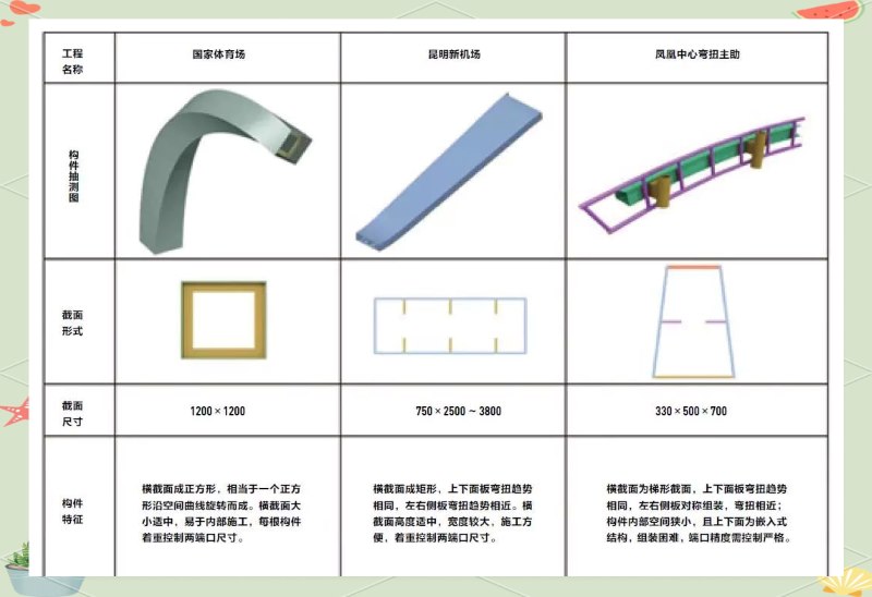
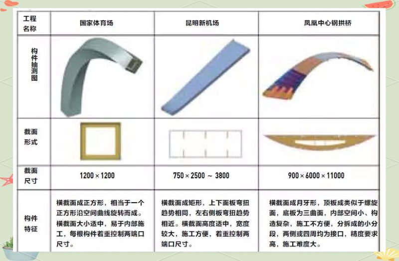
Comparison of the torsional component parameters of the "Phoenix Center" with the National Stadium and Kunming Airport
When discussing the design of the steel structure canopy for the "Phoenix Center" project, it is worthwhile to compare the composition of its main and secondary torsional ribs with similar components from the National Stadium and Kunming Airport. Such a comparison will help us gain a deeper understanding of the design concepts and implementation details of torsional components in different architectural projects.
After understanding the processing flow you introduced, I realized how workers obtain information from two-dimensional drawings to process the steel. However, I am still curious about the forming process of the hyperbolic structural ribs. How are these complex structural ribs ensured to perfectly fit the design shape during the process of welding steel strips into quadrilateral steel structural ribs?
Gao Jiling: Indeed, this is a significant challenge we faced in the "Phoenix Center" project. Although workers process according to two-dimensional drawings, what ultimately presents itself is a hyperbolic steel structure beam. This is where our carefully developed "processing and forming technology for spatial torsional components" comes into play.
The "Phoenix Center" project can be considered the most complex challenge our company has faced to date. Aside from the trusses of the entrance canopy and a few concrete structural support members, all other components are curved, whether in planar torsion or spatial torsion, with almost no horizontal or vertical components. Among them, the main ribs of the building's outer wall are particularly tricky, with a trapezoidal cross-section that is small in size, 750 mm in height and 330 to 500 mm in width, and formed by the splicing of four steel plates, creating a spatial three-dimensional torsional structure, with a plate thickness of up to 115 mm, making the processing difficulty unprecedented. Although the bending of the secondary ribs is relatively simple, the complexity of the main ribs is still beyond imagination. In addition, the two indoor ring slope structures resembling "bridges," though not large in size, present unprecedented complexity: both the planar and vertical dimensions are curved, and the cross-section is crescent-shaped, resulting in a unique "saddle surface" at the bottom.
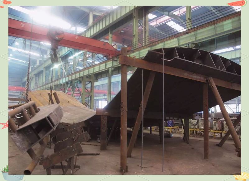
The final processing technology for the main ribs is not entirely innovative but draws on traditional shipbuilding techniques. The bow and stern of the ship's hull adopt three-dimensional spatial bending shapes, a technology that has been maturely applied in shipbuilding. However, the main ribs of the "Phoenix Center" consist of four steel "strips," which require precise splicing, undoubtedly increasing the complexity of processing. Although we employed similar technology in the "Bird's Nest" project, the number of curved components at that time was limited, and the cross-sections were larger. In contrast, the steel structure cross-section of the "Phoenix Center" is smaller, with thicker steel plates, and the total length of the torsional plates exceeds 30,000 meters. This means that to complete the processing of all main ribs, we must splice over 30,000 meters of plates accurately and efficiently. Therefore, our main challenges focus on precision and progress.
In facing the complex challenges of the "Phoenix Center" project, we cleverly applied "shipbuilding" technology and created a "sample box," or "inner mold." This inner mold was made according to the profile of the trapezoidal cross-section main ribs, removing the plate thickness to form a hollow structure. In this way, we can visually check the forming accuracy of the steel plates without complex measuring tools.
Traditional measuring methods, such as steel tapes and total stations, are inadequate when facing three-dimensional spatial torsional structures. However, with the "sample box" inner mold, we only need to compare the formed steel plates with it to quickly assess their accuracy. If the steel plate closely fits the inner mold, it indicates high processing accuracy; if there are gaps, reshaping is required.
This method of checking accuracy is not only simple and intuitive but also reduces the requirement for specialized skills. Ordinary workers can efficiently complete this task, significantly improving production efficiency.
For the accuracy check after the torsional plate forming, we rely on the carefully crafted "sample box inner mold." So how does this inner mold ensure that the outer skin's curvature strictly follows the design and avoids "deformation"? How does it accurately reflect the three-dimensional data in the design?
Gao Jiling explained that torsional ribs have a normal surface, meaning that the cross-section perpendicular to the normal is always a standard cross-section. These normal surfaces have clear dimensions; for example, the trapezoidal cross-section dimensions are (700 - 750) × 350 mm. As long as cutting is done on the normal surface, a standard cross-section can be obtained. If cutting deviates from the normal surface, even a slight deviation will result in an irregular cross-section.
When processing long main ribs, we find a normal surface every 500 or 800 millimeters, which makes the cross-section very convenient to produce. We create normal surface frames using small wooden strips, and these frames are twisted relative to each other, forming multiple normal surfaces. Although the twisting angle is easy to control in theoretical models, caution is still required in practical operations. After completing the twisting angle production, we connect the four corner points to form the desired twisted surface. It is worth noting that the frames of the normal surfaces are very sturdy, while the plywood connecting them is softer, so we nail the plywood according to the twisting of the normal surface frames, allowing for the natural formation of an accurate twisted surface.
Sample Box Production Process
In the accuracy inspection process of the twisted board, we not only rely on the carefully crafted "sample box liner," but also need to go through a series of complex sample box production processes. These processes ensure that the curvature of the outer skin strictly follows the design, thus avoiding the occurrence of "deformation." By precisely reflecting the three-dimensional data in the design, the sample box becomes an important basis for verifying the accuracy of the twisted board after shaping.
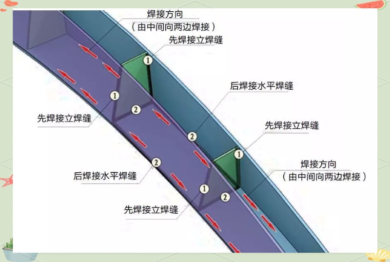
Steel Plate Welding Sequence
In the previous "shipbuilding" process, we employed a similar technique. However, the forming of the ship's wall steel plates is relatively simple, completed by rolling and pressing using an oil press or three-roll bending machine. However, accurately inspecting the forming effect remains a challenge. Without proper methods, construction supervision may struggle to assess the accuracy of the steel plate forming. With the tool of the "sample box," we can intuitively inspect the forming effect of each steel plate, ensuring that every bend and twist meets design requirements.
For the complex bends and twists in construction, we do need to create a "sample box" for each steel beam. During the steel structure production process of the "Phoenix Center," we used both wooden and steel "sample boxes" for inspection. This way, regardless of the total length of the main rib, we can ensure that every bend and twist is precise through the "sample box."
Additionally, our "woodworking workshop" plays a key role in this process. Although the cost of high-level carpentry is relatively high, it is their exquisite skills that ensure the reliability of the process. This unique craftsmanship not only reflects our commitment to tradition and manual techniques but also demonstrates significant advantages in actual engineering. During the splicing of multiple steel plates, we can achieve smooth, gapless welds, ensuring high precision and quality of the overall structure.
This process, while seemingly traditional, exhibits efficiency and precision in practical applications. Compared to some "advanced" technologies that rely on high-tech equipment, it may not have an advantage in initial investment, but its uniqueness lies in its dependence on the skilled craftsmanship of each worker. It is this "traditional" manual craftsmanship that allows us to achieve smooth, gapless welds, ensuring high precision and quality of the overall structure.
The steel plate welding process includes: first setting up the frame, then positioning the bottom plate of the main body, followed by the positioning of internal partitions and side plates. After that, the positioning of the cover plate and welding of the internal partitions are carried out. Once these steps are completed, the side sealing plates are positioned and the main welds of the box body are welded. Next, the installation positioning of components and welding of the steel plates are performed. Finally, integrity acceptance and pre-assembly are conducted.
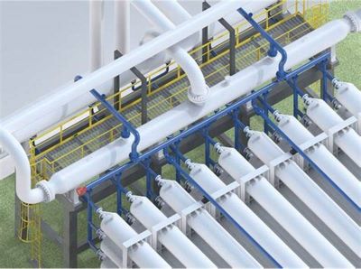
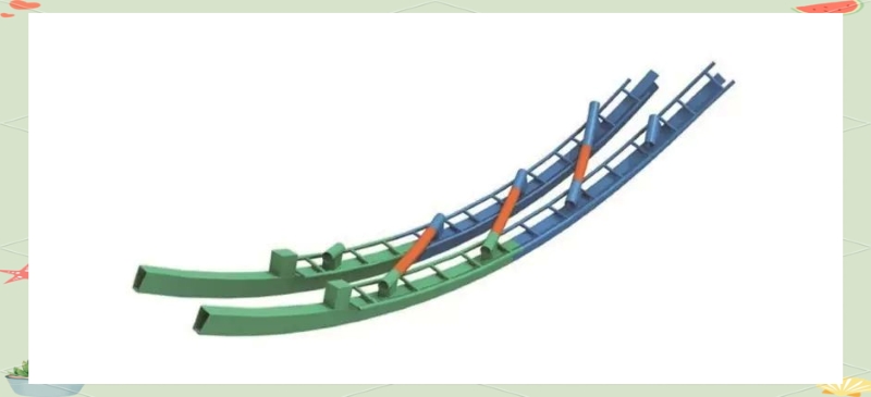
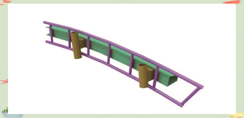
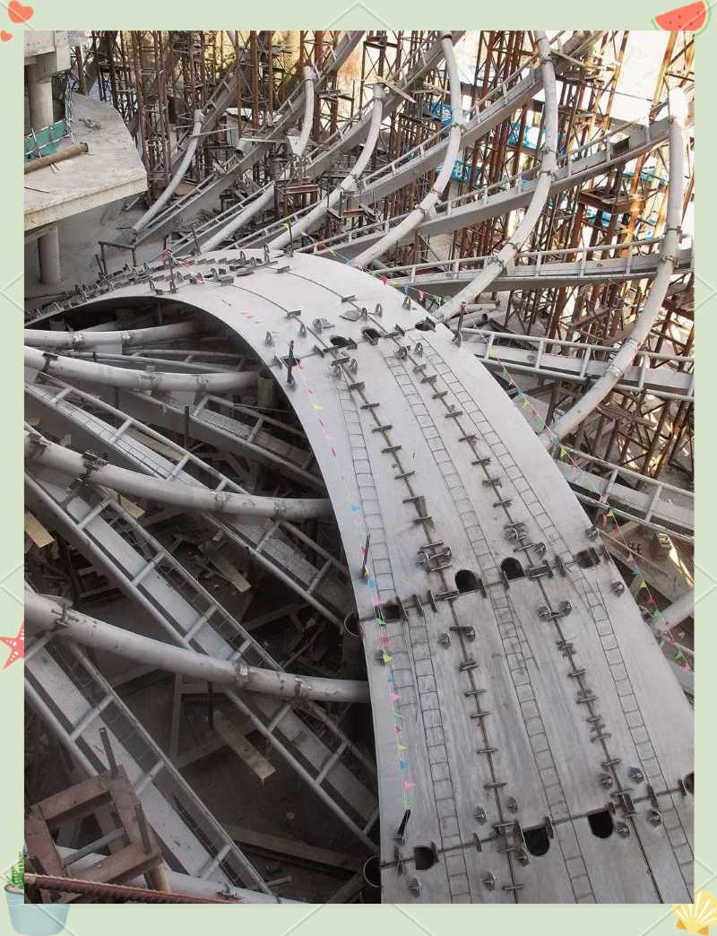
In the bridge manufacturing process, we adopted a "reverse construction" method. Due to the difficulty in positioning the saddle surface at the bottom of the bridge, we observed that the "unidirectional" arc surface on the upper side is simpler, so we decided to "flip" the bridge over for production. This way, with the bottom surface facing up and the top surface facing down, positioning during production becomes simpler. We first created transverse and longitudinal "hard blocks," which serve as internal supporting wooden ribs of the sample box. By precisely designing the arc lines on the upper surfaces of these wooden ribs, we can easily create tangents that intersect with the saddle surface perpendicularly. Then, we tightly nailed flexible plywood onto the hard blocks, forming a very precise hyperbolic arc surface.
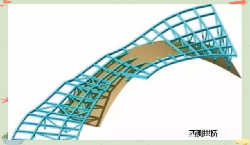
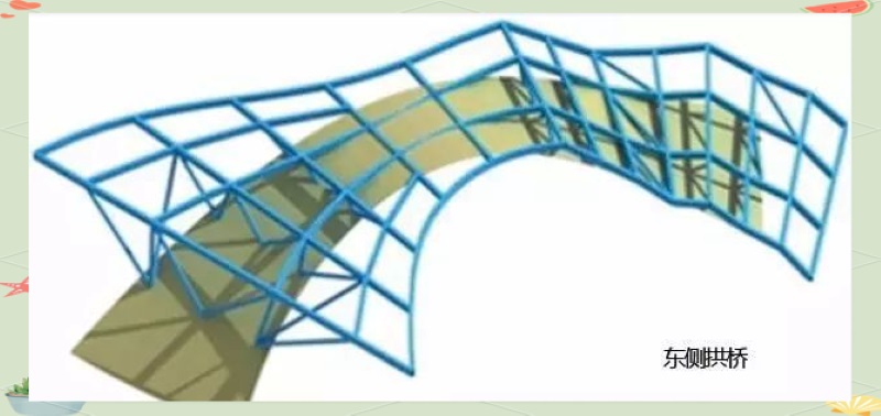
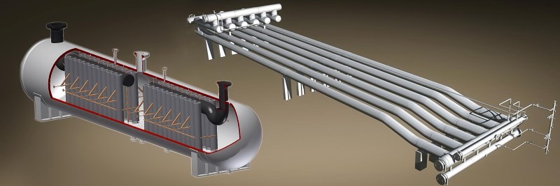
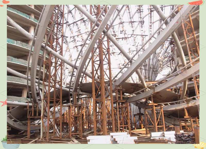
The steel arch bridge presents a "saddle-shaped" box structure, characterized by its unique cross-sectional design and parabolic arch shape along its length. The cross-section is a gradient crescent shape, varying in width from 6 to 11 meters, while the height in the middle of the cross-section remains at 0.9 meters. Additionally, the projections of the bridge surface inside and outside present irregular arcs, making the overall design of the bridge both aesthetically pleasing and practical. The total weight of a single steel arch bridge is approximately 300 tons, with a length of 42 meters; its top plate approximates a slanted conical surface, while the bottom plate presents a saddle-shaped surface, together forming this unique steel arch bridge.
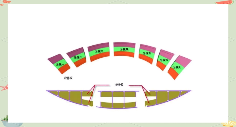
Segmented Processing
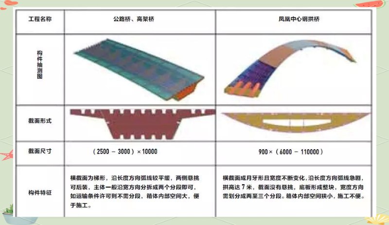
Comparison with Other Projects
Pre-assembly Plan
Construction Process
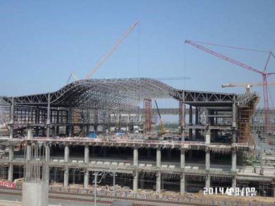
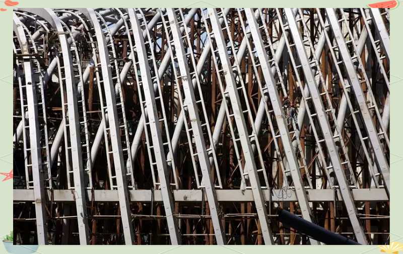
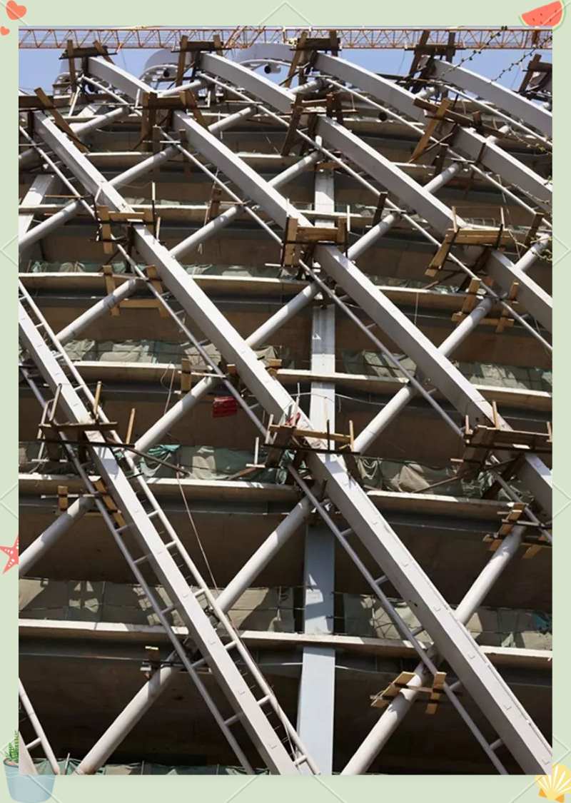
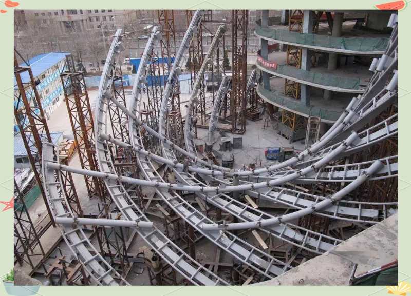
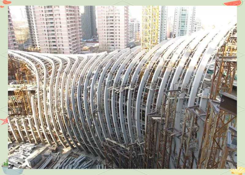
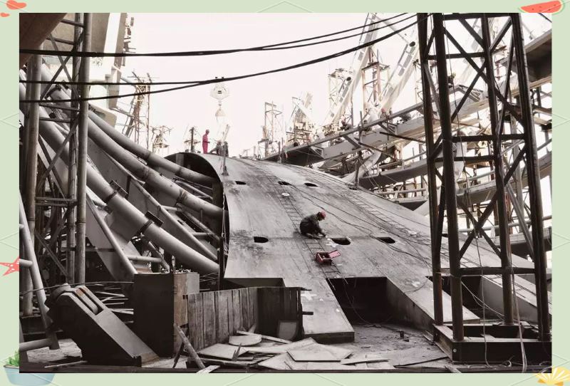
On-site Installation of Steel Structure Arch Bridge
Construction Challenges and Breakthroughs of Steel Structure Arch Bridge
October 27, 2010, Official Start of Steel Structure Construction
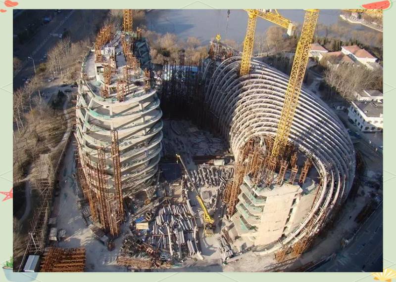
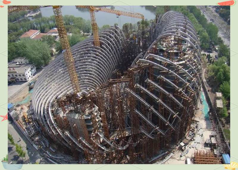
Revealing the Steel Structure Construction Process
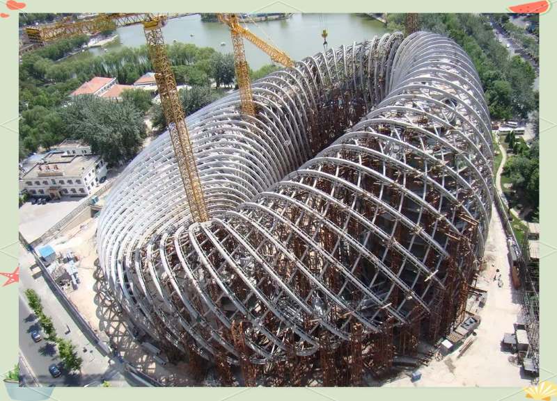
Successful Completion of Steel Structure Construction
Today, in the lobby of the "ZHM Huawu Steel Structure" headquarters, the model of the "Phoenix Center" still occupies the most prominent position. It not only attracts countless visitors but has also become a truly original work, providing endless shock and imagination to people. Although we have undertaken many large projects, the model of the "Phoenix Center" always stands out among these models, showcasing its extraordinary charm.
Why ZHM Huawu large span Office Buildings?
 |
 |
 |
 |
| Reliable and Customized Designs | Cutting Edge Designing Process | Free Online Price System | Easy Bolt-by-number Assembly |
 |
 |
 |
 |
| Over Two Decades of Experience | Value For Money | Unmatched in Quality and Craftmanship | Excellent Customer Service |
Would you like to see more information and images of ZHM Huawu Steel's large span Office Buildings ? Visit our Photo Gallery.
HOW CAN WE HELP YOU?
ZHM’s world-class team — together with our raw material suppliers and subcontractors — works to solve your most challenging design, engineering, farbrication or construction issues.
Contact ZHM by telephone at +86 135-8815-1981 (wechat and whatsapp) or send us your questions via email to info@zhmsteelworks.com