Shenyang South Central Station Roof Large Span Arched Steel Structure
2025-6-29 22:12:59
Shenyang South Central
Introduction
Shenyang South Central Station Roof Large Span Arched Steel Structure
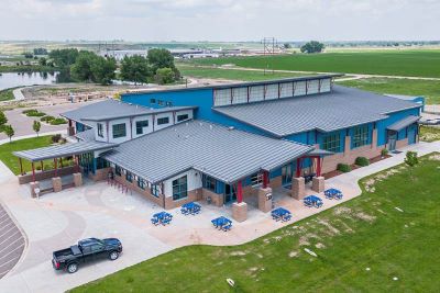
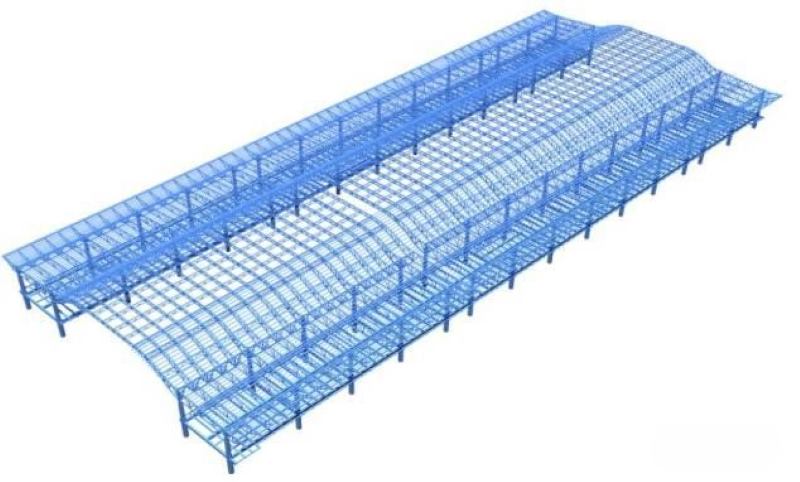
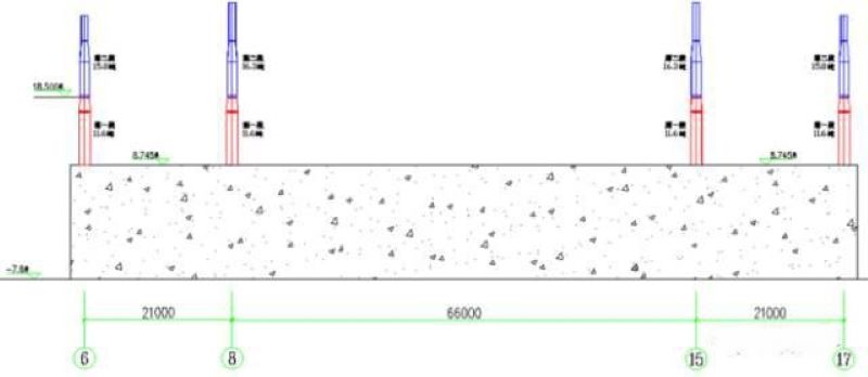
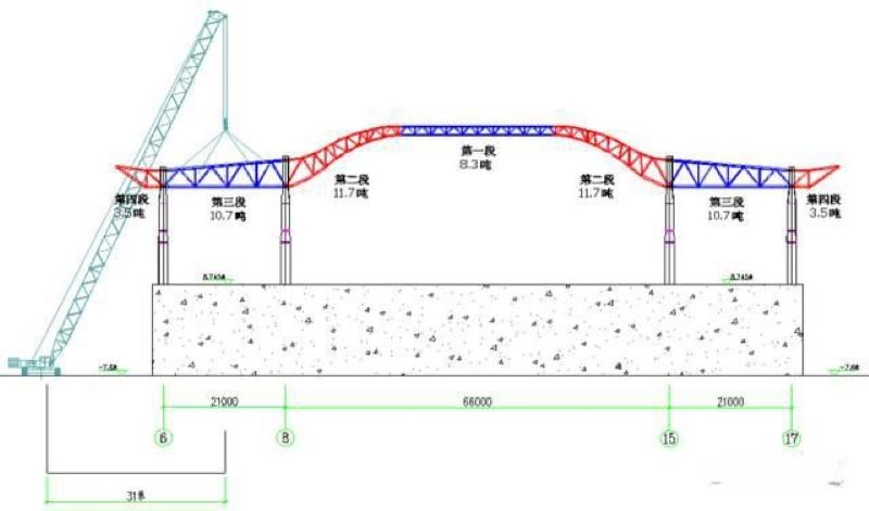
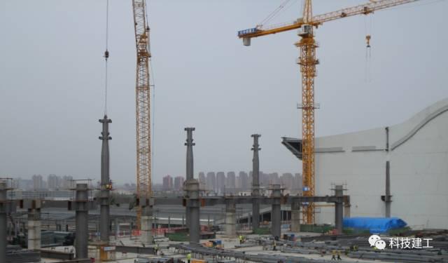
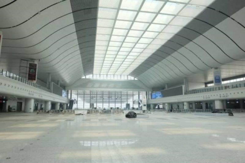
Overview: The steel truss structure of the roof at Shenyang South Station, prefabricated constructed by ZHM, has a length of 286.5m from east to west, with a north-south span of 21m + 66m + 21m and an 8.0m cantilever on both sides. The basic column grid is 10.5m × 21.5m and 10.5m × 24m. The elevation of the elevated layer structure is 8.745m, the elevation of the mezzanine structure is 16.400m, and the roof structure elevation ranges from 29.91m to 37.51m (see Figure 1).
Plan Selection
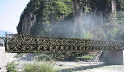
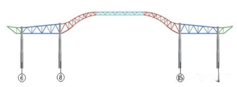
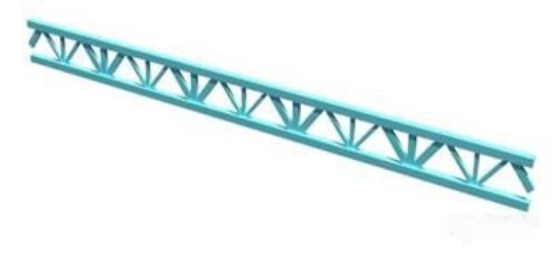
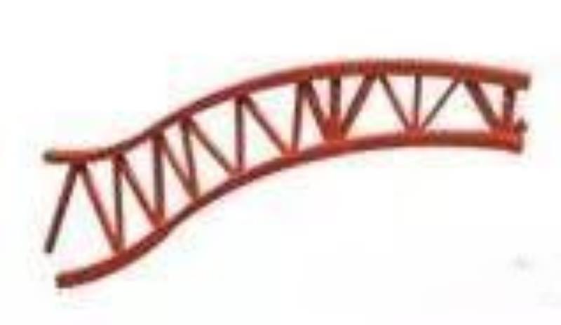
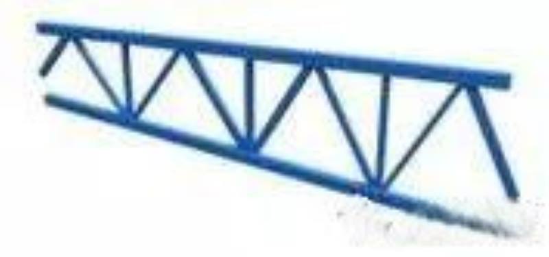
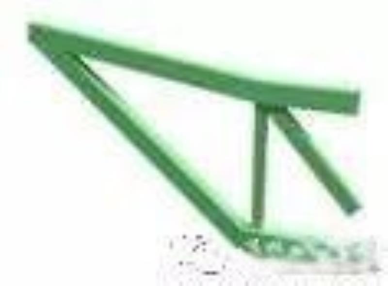
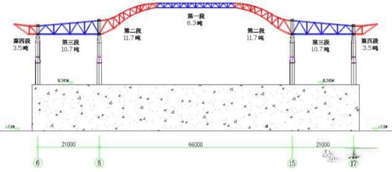
The span between columns 8 to 15 in the central station reaches 66m, with a total component weight of 31.7t, and the overall arching height of the truss at the top of the columns is approximately 9.45m (see Figures 2-6).
The installation plan for the arch truss of the central station can be carried out using either a whole lifting method or a segmented hoisting method, each with its own advantages and disadvantages.
Plan one is the segmented hoisting method. The advantages of this plan are: multiple working surfaces for the main truss can be pre-assembled on the ground, which is beneficial for ensuring the construction schedule; minimal impact on the lower concrete floor; reusable support frame with low input; and minimal influence of internal force changes in truss members during the roof structure formation process. The disadvantages are: larger construction machinery models, resulting in higher costs; relatively more high-altitude construction work.
Plan two is the whole lifting method. The advantages of this plan are: high quality of overall assembly; less high-altitude construction work. The disadvantages are: the concrete floor at the 9m level must reach the design strength before truss assembly can begin, which is not favorable for the overall construction schedule; floor assembly occupies a large amount of working space, which is not conducive to other work; the high arching of the truss requires a significant amount of scaffolding during assembly, and the lifting to completion can be seen as a process where the truss transforms from a simply supported beam into a continuous beam, resulting in significant changes in internal forces of structural members.
Considering the overall tight construction schedule and the more favorable changes in internal forces of structural components, as well as cost savings, Plan one, the segmented hoisting method, was selected after comprehensive comparison. The truss between columns 8 to 15 in the central station can be divided into 3 segments for hoisting. There is no lower column support at the segmentation points, so a support frame needs to be erected.
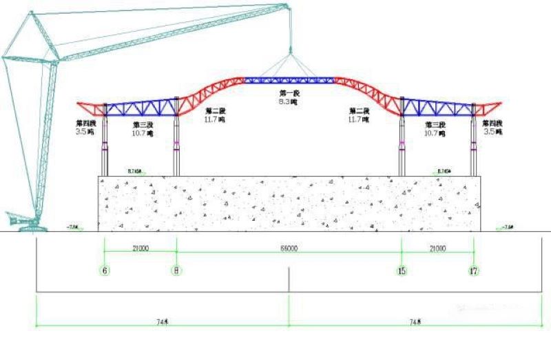
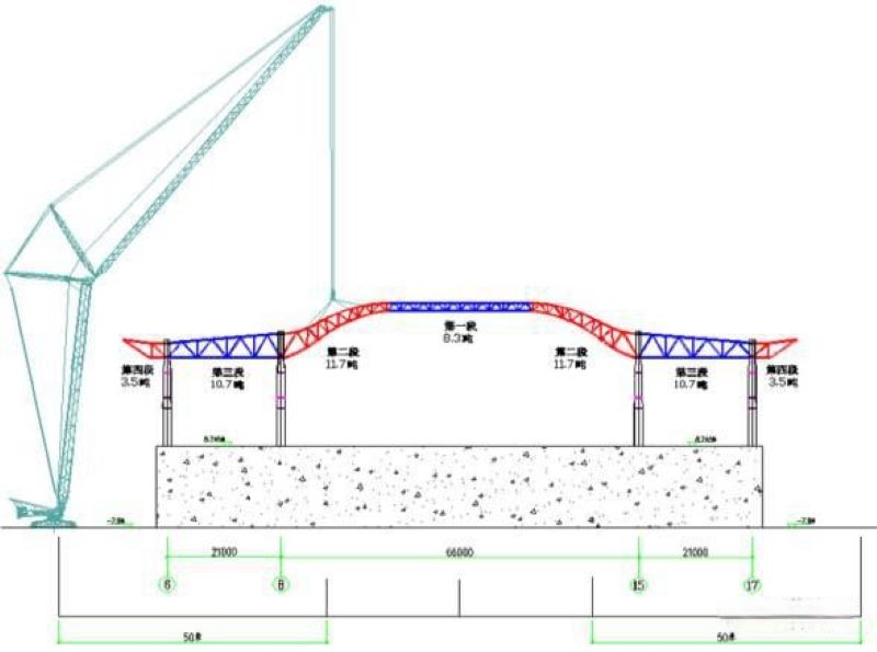
A 400t crawler crane is used to hoist steel columns, mezzanine beams, and the transverse main trusses at axes 6-8 and 15-17, as well as the longitudinal main trusses, forming a stable structural system. Then, the transverse secondary trusses, longitudinal secondary trusses, and cantilevered segment units (i.e., segmented one) in that area are hoisted. The 66m span transverse truss is divided into three segments for hoisting, with support frames set at the segmentation points, and the height of the support frame is 26.9m. During construction, the support frame is reused, but it is necessary to retain the support frame within the longitudinal spacing of two columns to prevent excessive deformation before the overall structure takes shape.
Plan Verification and Implementation
3.1 Acceptance and Implementation of the Central Roof Steel Structure Plan
3.1.1 Steel Structure Hoisting Weight Verification
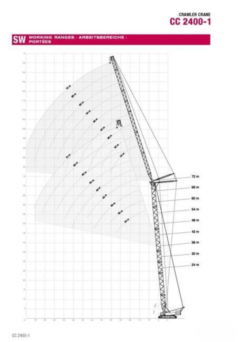
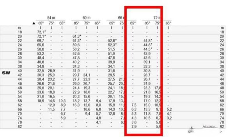
▲ Figure 7 48m main arm + 72m auxiliary arm tower condition
(2) Steel Column Hoisting Weight Verification
The steel pipe concrete column cross-section below the elevated mezzanine at an elevation of 16.280m is P1600×35, and the steel column cross-section above the elevated mezzanine at 16.280m is P1400×35. Based on the distribution characteristics of the steel columns and the performance of the crawler crane, the steel columns are divided into two segments, with the segmentation position at an elevation of 18.500m.
The hoisting condition analysis for the second segment of the intermediate column, which has the highest hoisting performance requirements, meets the hoisting requirements.
(3) Main Truss Hoisting Weight Verification
This project uses two 400-ton crawler cranes on both sides of the station building for hoisting the main trusses. The transverse main and secondary trusses are divided into 7 segments, with the 66m span truss divided into 3 segments and each side span divided into 2 segments (see Figure 9).
Analysis of the hoisting condition for the first segment (see Figure 10, see Table 1).
▼ Table 1 Analysis table of the hoisting condition for the first segment
Analysis of the hoisting condition for the second segment (see Figure 11, see Table 2).
▼ Table 2 Analysis table of the hoisting condition for the second segment
Analysis of the lifting conditions for the third segment (see Figure 12, see Table 3).
▼ Table 3 Analysis of lifting conditions for the third segment
3.1.2 Analysis of the construction process and implementation of the plan
(1) Explanation of force and deformation simulation during the construction process
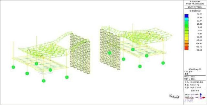
The installation of the steel structure is a gradually accumulated process, during which the forces and boundary conditions of the structure change over time. Therefore, the maximum internal force state or final state of the components may differ significantly from the overall structural analysis results obtained during the design due to different construction techniques or sequences. To ensure the safety of the steel roof structure during the construction process and after installation, a construction process simulation analysis is necessary. The construction process analysis was conducted using the large-scale general finite element software MIDAS GEN/8.0, yielding the internal forces and deformation conditions during the construction of the steel structure.
(2) Calculation model
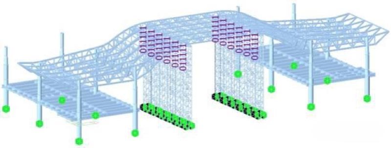
Since the structural units of the central station building are arranged similarly in the east-west direction, a typical unit (the most unfavorable) is selected for construction simulation (frame II-J axis to II-K axis, roof truss II-J axis to II-K axis) (see Figure 13).
Structural units.
Concrete-filled steel tube columns use SRC materials and structures, while the supporting frame's web members use truss elements, and the rest are simulated using beam elements.
Loading conditions.
Based on the solid model, the self-weight coefficient is set to 1.0.
Purlins and purlin supports are loaded as line loads on the corresponding upper chords of the transverse trusses, with an equivalent load of 1.53 kN/m.
The skylight glass frame is loaded as nodal loads on the upper chord nodes of the longitudinal and transverse trusses below the skylight, with an equivalent load of 5.0 kN.
Boundary conditions.
The bottom of the concrete-filled steel tube columns is rigidly connected.
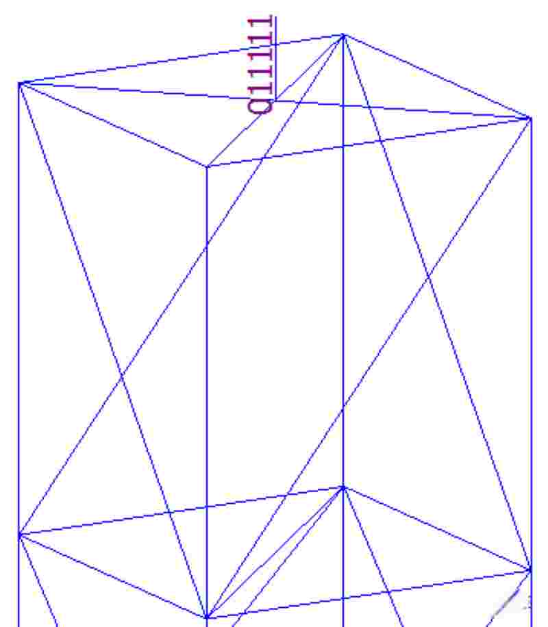
The bottom of the supporting frame is hinged, without considering the beneficial effects of bottom reinforcement measures; Y, Z direction, and angular constraints are released at the top of the supporting frame (see Figure 14).
(3) Analysis of the construction process and implementation of the plan
Step one: Lift the concrete-filled steel tube columns and floor steel beams.
▼ On-site implementation diagram
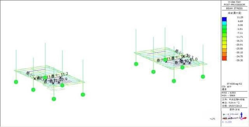
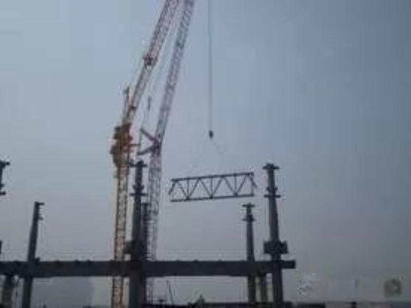
Step two: Install the main roof truss to form a stable frame.
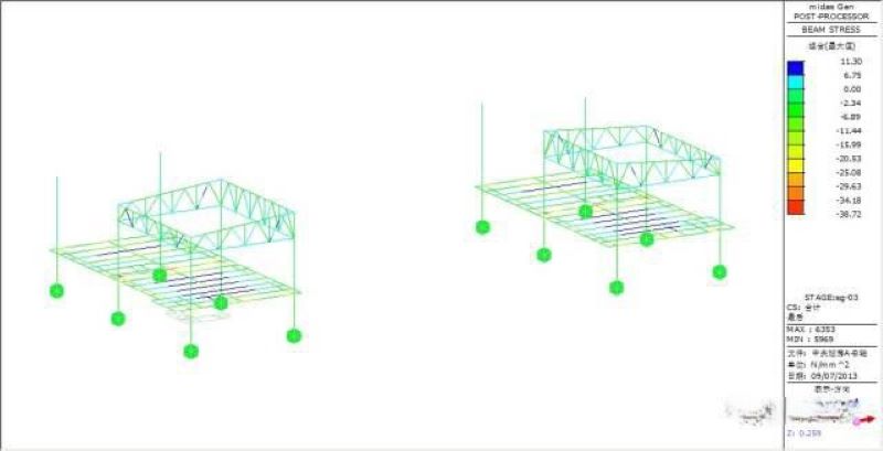
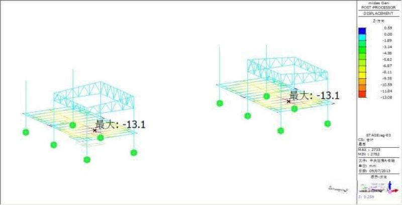
Force and deformation analysis: The maximum vertical deformation is 13.1 mm, occurring at the floor steel beams, with small vertical deformation in the trusses; the maximum stress in the members is 38.72 MPa.
▼ On-site implementation diagram
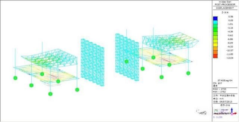
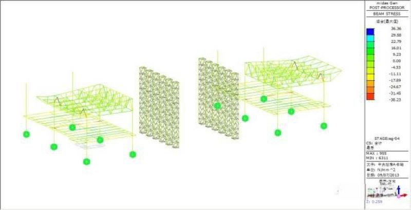
Step three: Install the secondary roof trusses to form a complete structure; build a supporting frame at an elevation of 8.745 m.
Force and deformation analysis: The maximum vertical deformation is 13.04 mm, occurring at the floor steel beams, with small vertical deformation in the trusses; the maximum stress in the members is 38.23 MPa.
▼ On-site implementation diagram
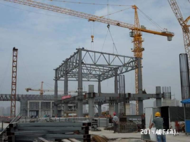
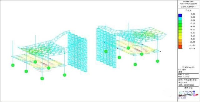
Step four: Install the second segment of the truss at the midspan of the roof.
Force and deformation analysis: The maximum vertical deformation is 13.05 mm, occurring at the floor steel beams, with small vertical deformation in the trusses; the maximum stress in the members is 38.53 MPa.
▼ On-site implementation diagram

Step five: Install the first segment of the truss at the midspan of the roof.
Force and deformation analysis: The maximum vertical deformation is 13.05 mm, occurring at the floor steel beams, with small vertical deformation in the trusses; the maximum stress in the members is 38.49 MPa.
▼ On-site implementation diagram
Step six: Install the transverse secondary trusses at the midspan of the roof.
Force and deformation analysis: The maximum vertical deformation is 13.04 mm, occurring at the floor steel beams, with small vertical deformation in the trusses; the maximum stress in the members is 38.51 MPa.
▼ On-site implementation diagram
Step seven: Install the longitudinal secondary trusses at the midspan of the roof.
Force and deformation analysis: The maximum vertical deformation is 13.04 mm, occurring at the floor steel beams, with small vertical deformation in the trusses; the maximum stress in the members is 38.5 MPa.
▼ On-site implementation diagram
Step eight: Unload the roof and dismantle the supporting frame.
Force and deformation analysis: The maximum vertical deformation is 27.2 mm; the maximum stress in the members is 45.2 MPa.
▼ On-site implementation diagram
Step nine: Install purlins and skylights.
Force and deformation analysis: The maximum vertical deformation is 36 mm; the maximum stress in the members is 47.51 MPa.
▼ On-site implementation diagram
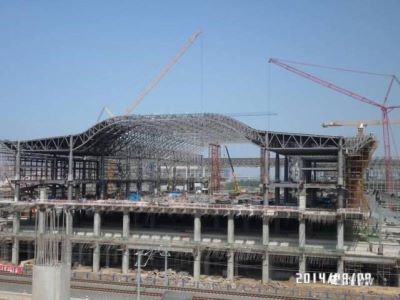
(1) The 66 m span large-span steel truss of the central station building adopts a segmented lifting and high-altitude closure lifting scheme, completing the lifting of 12,000 tons of steel structure in a total of 4 months for segments C and D, laying a solid foundation for ensuring the overall construction progress of the project.
(2) During the construction of this project’s large-span steel structure truss, the maximum structural deformation was 36mm, and the maximum stress was 45.51MPa. Both the structural deformation and stress meet the specifications and design requirements. Compared to the one-time forming of the structure, the segmented hoisting construction resulted in an additional deformation of 1.9mm and an additional stress of 1.2MPa, both of which are relatively small and meet construction requirements. The segmented hoisting and high-altitude closure hoisting schemes are safe and reasonable.
Overview: The steel truss structure of the roof at Shenyang South Station, prefabricated constructed by ZHM, has a length of 286.5m from east to west, with a north-south span of 21m + 66m + 21m and an 8.0m cantilever on both sides. The basic column grid is 10.5m × 21.5m and 10.5m × 24m. The elevation of the elevated layer structure is 8.745m, the elevation of the mezzanine structure is 16.400m, and the roof structure elevation ranges from 29.91m to 37.51m (see Figure 1).
Plan Selection
The span between columns 8 to 15 in the central station reaches 66m, with a total component weight of 31.7t, and the overall arching height of the truss at the top of the columns is approximately 9.45m (see Figures 2-6).
The installation plan for the arch truss of the central station can be carried out using either a whole lifting method or a segmented hoisting method, each with its own advantages and disadvantages.
Plan one is the segmented hoisting method. The advantages of this plan are: multiple working surfaces for the main truss can be pre-assembled on the ground, which is beneficial for ensuring the construction schedule; minimal impact on the lower concrete floor; reusable support frame with low input; and minimal influence of internal force changes in truss members during the roof structure formation process. The disadvantages are: larger construction machinery models, resulting in higher costs; relatively more high-altitude construction work.
Plan two is the whole lifting method. The advantages of this plan are: high quality of overall assembly; less high-altitude construction work. The disadvantages are: the concrete floor at the 9m level must reach the design strength before truss assembly can begin, which is not favorable for the overall construction schedule; floor assembly occupies a large amount of working space, which is not conducive to other work; the high arching of the truss requires a significant amount of scaffolding during assembly, and the lifting to completion can be seen as a process where the truss transforms from a simply supported beam into a continuous beam, resulting in significant changes in internal forces of structural members.
Considering the overall tight construction schedule and the more favorable changes in internal forces of structural components, as well as cost savings, Plan one, the segmented hoisting method, was selected after comprehensive comparison. The truss between columns 8 to 15 in the central station can be divided into 3 segments for hoisting. There is no lower column support at the segmentation points, so a support frame needs to be erected.
A 400t crawler crane is used to hoist steel columns, mezzanine beams, and the transverse main trusses at axes 6-8 and 15-17, as well as the longitudinal main trusses, forming a stable structural system. Then, the transverse secondary trusses, longitudinal secondary trusses, and cantilevered segment units (i.e., segmented one) in that area are hoisted. The 66m span transverse truss is divided into three segments for hoisting, with support frames set at the segmentation points, and the height of the support frame is 26.9m. During construction, the support frame is reused, but it is necessary to retain the support frame within the longitudinal spacing of two columns to prevent excessive deformation before the overall structure takes shape.
Plan Verification and Implementation
3.1 Acceptance and Implementation of the Central Roof Steel Structure Plan
3.1.1 Steel Structure Hoisting Weight Verification
▲ Figure 7 48m main arm + 72m auxiliary arm tower condition
(2) Steel Column Hoisting Weight Verification
The steel pipe concrete column cross-section below the elevated mezzanine at an elevation of 16.280m is P1600×35, and the steel column cross-section above the elevated mezzanine at 16.280m is P1400×35. Based on the distribution characteristics of the steel columns and the performance of the crawler crane, the steel columns are divided into two segments, with the segmentation position at an elevation of 18.500m.
The hoisting condition analysis for the second segment of the intermediate column, which has the highest hoisting performance requirements, meets the hoisting requirements.
(3) Main Truss Hoisting Weight Verification
This project uses two 400-ton crawler cranes on both sides of the station building for hoisting the main trusses. The transverse main and secondary trusses are divided into 7 segments, with the 66m span truss divided into 3 segments and each side span divided into 2 segments (see Figure 9).
Analysis of the hoisting condition for the first segment (see Figure 10, see Table 1).
▼ Table 1 Analysis table of the hoisting condition for the first segment
Analysis of the hoisting condition for the second segment (see Figure 11, see Table 2).
▼ Table 2 Analysis table of the hoisting condition for the second segment
Analysis of the lifting conditions for the third segment (see Figure 12, see Table 3).
▼ Table 3 Analysis of lifting conditions for the third segment
3.1.2 Analysis of the construction process and implementation of the plan
(1) Explanation of force and deformation simulation during the construction process
The installation of the steel structure is a gradually accumulated process, during which the forces and boundary conditions of the structure change over time. Therefore, the maximum internal force state or final state of the components may differ significantly from the overall structural analysis results obtained during the design due to different construction techniques or sequences. To ensure the safety of the steel roof structure during the construction process and after installation, a construction process simulation analysis is necessary. The construction process analysis was conducted using the large-scale general finite element software MIDAS GEN/8.0, yielding the internal forces and deformation conditions during the construction of the steel structure.
(2) Calculation model
Since the structural units of the central station building are arranged similarly in the east-west direction, a typical unit (the most unfavorable) is selected for construction simulation (frame II-J axis to II-K axis, roof truss II-J axis to II-K axis) (see Figure 13).
Structural units.
Concrete-filled steel tube columns use SRC materials and structures, while the supporting frame's web members use truss elements, and the rest are simulated using beam elements.
Loading conditions.
Based on the solid model, the self-weight coefficient is set to 1.0.
Purlins and purlin supports are loaded as line loads on the corresponding upper chords of the transverse trusses, with an equivalent load of 1.53 kN/m.
The skylight glass frame is loaded as nodal loads on the upper chord nodes of the longitudinal and transverse trusses below the skylight, with an equivalent load of 5.0 kN.
Boundary conditions.
The bottom of the concrete-filled steel tube columns is rigidly connected.
The bottom of the supporting frame is hinged, without considering the beneficial effects of bottom reinforcement measures; Y, Z direction, and angular constraints are released at the top of the supporting frame (see Figure 14).
(3) Analysis of the construction process and implementation of the plan
Step one: Lift the concrete-filled steel tube columns and floor steel beams.
▼ On-site implementation diagram
Step two: Install the main roof truss to form a stable frame.
Force and deformation analysis: The maximum vertical deformation is 13.1 mm, occurring at the floor steel beams, with small vertical deformation in the trusses; the maximum stress in the members is 38.72 MPa.
▼ On-site implementation diagram
Step three: Install the secondary roof trusses to form a complete structure; build a supporting frame at an elevation of 8.745 m.
Force and deformation analysis: The maximum vertical deformation is 13.04 mm, occurring at the floor steel beams, with small vertical deformation in the trusses; the maximum stress in the members is 38.23 MPa.
▼ On-site implementation diagram
Step four: Install the second segment of the truss at the midspan of the roof.
Force and deformation analysis: The maximum vertical deformation is 13.05 mm, occurring at the floor steel beams, with small vertical deformation in the trusses; the maximum stress in the members is 38.53 MPa.
▼ On-site implementation diagram
Step five: Install the first segment of the truss at the midspan of the roof.
Force and deformation analysis: The maximum vertical deformation is 13.05 mm, occurring at the floor steel beams, with small vertical deformation in the trusses; the maximum stress in the members is 38.49 MPa.
▼ On-site implementation diagram
Step six: Install the transverse secondary trusses at the midspan of the roof.
Force and deformation analysis: The maximum vertical deformation is 13.04 mm, occurring at the floor steel beams, with small vertical deformation in the trusses; the maximum stress in the members is 38.51 MPa.
▼ On-site implementation diagram
Step seven: Install the longitudinal secondary trusses at the midspan of the roof.
Force and deformation analysis: The maximum vertical deformation is 13.04 mm, occurring at the floor steel beams, with small vertical deformation in the trusses; the maximum stress in the members is 38.5 MPa.
▼ On-site implementation diagram
Step eight: Unload the roof and dismantle the supporting frame.
Force and deformation analysis: The maximum vertical deformation is 27.2 mm; the maximum stress in the members is 45.2 MPa.
▼ On-site implementation diagram
Step nine: Install purlins and skylights.
Force and deformation analysis: The maximum vertical deformation is 36 mm; the maximum stress in the members is 47.51 MPa.
▼ On-site implementation diagram
(1) The 66 m span large-span steel truss of the central station building adopts a segmented lifting and high-altitude closure lifting scheme, completing the lifting of 12,000 tons of steel structure in a total of 4 months for segments C and D, laying a solid foundation for ensuring the overall construction progress of the project.
(2) During the construction of this project’s large-span steel structure truss, the maximum structural deformation was 36mm, and the maximum stress was 45.51MPa. Both the structural deformation and stress meet the specifications and design requirements. Compared to the one-time forming of the structure, the segmented hoisting construction resulted in an additional deformation of 1.9mm and an additional stress of 1.2MPa, both of which are relatively small and meet construction requirements. The segmented hoisting and high-altitude closure hoisting schemes are safe and reasonable.