Gas Turbine Combined Cycle Waste Heat Recovery (WHR) Power Plants

Gas Turbine Combined Cy
Successful EPC Delivery of Gas Turbine Combined Cycle Waste Heat Recovery (WHR) Power Plants
This article focuses on the technical aspects, system integration, and operational parameters of two reference plants: a 1x22MW plant (Wassa/Chirano/Edikan) and a 2x22MW plant (Tarkwa). These projects convert gas turbine exhaust gas into valuable electricity, supporting gold mining operations while improving overall energy efficiency.
1. Project Background and Design Scope
Key design considerations:
▶Flue gas inlet temperature: 482°C – 513°C
▶Exhaust gas oxygen content: approx. 15% (requiring oxidation-resistant duct design)
▶Ambient conditions: tropical climate, seismic fortification intensity 7 degrees (0.1g)
The EPC scope included:
▶HRSG (Heat Recovery Steam Generator) – horizontal, natural circulation
▶Steam turbine generator (STG) – water-cooled condensing type
▶Balance of plant (BOP): cooling water system, chemical water treatment, electrical system, DCS process automation, and civil/structural works.
2. HRSG and Steam Parameter Integration
Boiler design parameters (per gas turbine):
| Parameter | 1#~3# HRSG | 4#~6# HRSG (Tarkwa) |
| Main steam pressure | 3.82 MPa(a) | 3.82 MPa(a) |
| Main steam temperature | 450°C | 450°C |
| Main steam flow | 23.1 t/h | 15.9 t/h |
| Exhaust gas temperature | 105°C | 108°C |
| Feed water temperature | 45°C | 45°C |
| Deaeration temperature | ~150°C | ~150°C |
|
|
|
|
The dual-pressure system (or single-pressure in Tarkwa) sends main steam and low-pressure supplementary steam to the turbine inlet, maximizing heat recovery. A desuperheater water control prevents main steam over-temperature when flue gas reaches 525–550°C.
3. Steam Turbine and Generator
Main turbine data (22MW unit):
▶Rated power: 22,000 kW (design point 18,280 kW / 15,250 kW)
▶Rated speed: 3,000 r/min
▶Main steam: 3.43 MPa(a) / 435°C
▶Exhaust pressure: 0.0095 MPa(a)
▶Axial exhaust design reduces civil works and installation time.
Generator:
▶Air-cooled, single-end support
▶Rated voltage: 11 kV
▶Excitation: SCR static excitation
▶Protection: stator/rotor/bearing temperature alarms
The turbine control uses DEH (Digital Electro-hydraulic) system, enabling remote start-up, forward pressure regulation, and load following despite fluctuating waste heat conditions.
4. Thermal and Auxiliary Systems
Cooling Water System
▶Circulation flow: 6,895 m³/h (1x22MW) / 15,590 m³/h (2x22MW)
▶Cooling towers: FRP, counter-flow, mechanical draft, VFD-controlled fans
▶Circulating pumps: Double-suction centrifugal (VFD)
▶Makeup water: 124.1 m³/h per plant
Chemical Water Treatment
▶Capacity: 15 m³/h (1x22MW) / 20 m³/h (2x22MW)
▶Outlet quality: Hardness ≤2.0 µmol/L, Fe ≤50 µg/L, Silica controlled to ≤20 µg/kg in steam.
Boiler Water Conditioning
▶Oxygen control: Thermal deaeration integrated in HRSG.
▶Chemical dosing: Na₃PO₄ injection for drum water pH adjustment.5. Electrical System and Grid Integration
Single-line configuration:
▶Generator voltage: 11 kV → 11 kV single busbar
▶Step-up to 34.5 kV via existing mine substation.
▶Two parallel connection lines to gas turbine station and main substation (interlocked to prevent simultaneous closure).
Key electrical features:
▶Fault current limiter: Required due to 30.321 kA short-circuit level at 11 kV bus.
▶Switchgear: Metal-clad, withdrawable, 40 kA rated breaking capacity.
▶Auxiliary transformer: SCB12-2000/11, 11/0.415 kV, 2000 kVA (load rate ~76%).
▶DC system: 220 VDC, 200 Ah (lead-acid, maintenance-free).
Protection and control:
▶Differential protection for generator and lines.
▶Digital synchronizing at generator and line breakers.
▶DCS-based centralized control (see section 6).
6. Process Automation (DCS and Instrumentation)
A Distributed Control System (DCS) provides centralized monitoring and control for:
▶Boiler drum level (TV monitor)
▶Hotwell and deaerator level
▶Steam temperature/pressure regulation
▶Group start/stop of motors and valves
Field instruments:
▶Smart pressure/differential pressure transmitters (HART protocol, ±0.075% accuracy)
▶Armored thermocouples (K-type) and Pt100 RTDs
▶UPS backup (15 kVA, 60 min) for control system reliability
Communication & dispatching: Interface with local power company for grid communication (owned scope).
7. Fire Protection, Lighting, and Explosive Atmosphere Compliance
▶Electrical fire prevention: Fire-resistant cable blocking, extractor fans in HV/LV rooms.
▶Explosive atmosphere design: Complies with GB standards (ExiaIIbT4 for boiler area instruments).
▶Illumination:
▶▶Normal: 415/240 V, uniform + local
▶▶Emergency: DC 220 V automatic switching
▶▶Safety: 24 VAC for boiler internal maintenance
8. Plant Layout and Civil/Structural Highlights
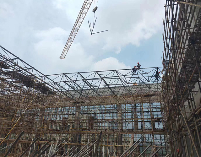
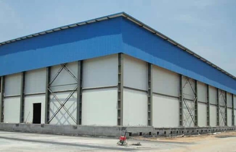
▶Main building: steel frame, single story (27x18m per turbine/generator hall).
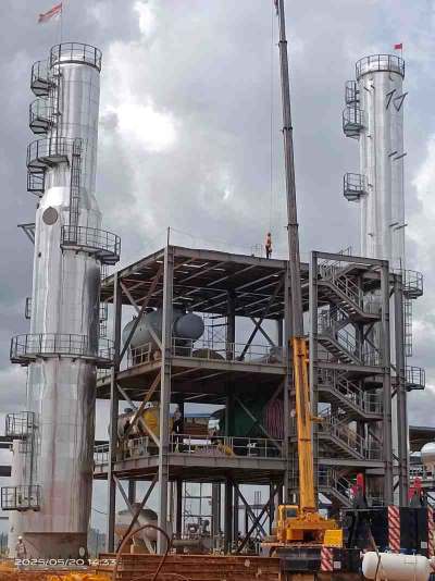
▶HRSG: outdoor, placed adjacent to gas turbine (short ducting, low pressure loss).▶Cooling tower area: 42x14m (per plant), with integral water pond.
▶Chemical water treatment: containerized (skid-mounted), plus outdoor tanks.
▶Architectural: composite steel cladding, acid-resistant flooring where required.
▶Seismic: 7-degree fortification (0.1g base acceleration).
9. Duct Insulation and High-Temperature Flue Gas Handling
Because of high oxygen content (approx. 15%) and exhaust temperatures up to 550°C, standard carbon steel is prone to oxidation. The design incorporates internal ceramic fiber insulation with a 1mm thick 304 stainless steel liner, secured by 304 nails. This approach significantly reduces investment cost compared to a full stainless steel flue.
10. Operational and Environmental Performance
| Indicator | 1x22MW Plant | 2x22MW Plant |
| Installed capacity | 22 MW | 2 x 22 MW |
| Design power generation | 18.28 MW | 15.25 MW per unit |
| Auxiliary power consumption | ~7% | ~7% |
| Total water consumption | 129.9 m³/h | 293.1 m³/h |
| Relative operation rate | 98% | 98% |
| Waste heat recovery rate | ~75% | ~75% |
|
|
|
|
Through disciplined EPC execution — from conceptual engineering, equipment manufacturing, site installation, to DCS commissioning — ZHM has demonstrated successful deployment of gas turbine combined cycle waste heat recovery power plants under real operating conditions in West Africa.
The technical solutions presented here (dual-pressure HRSG, axial exhaust turbine, VFD-driven cooling, 2-stage RO water treatment, and fault current limitation) are applicable to similar industrial settings where waste heat from gas turbines can be converted into reliable, grid-connected or captive power.
For further technical inquiries or EPC cooperation, please contact our engineering department.

1 Drone View Chirano CCGT WHR Power Plant

2 Chemical Water Tank Plant

3 HRSG Boiler Lifting

4 HRSG Drum Economizer Installation

5 Water Cooler System Pumps

6 Pipe Rack Cable Tray To STG Building

7 STG Shaft Bearing Installation

8 HRSG Boiler Lifting Hoisting 650ton Crawler Crane

9 HRSG Boiler Piping Instrument Installation

10 Waste Heat Recovery Boiler High Temp Drum Installation

11 Steam Turbine Generator Piping Instrument Installation

12 Overhead Bridge Pipe Rack Cable Tray Installation

13 Steam Turbine Generator System Installation

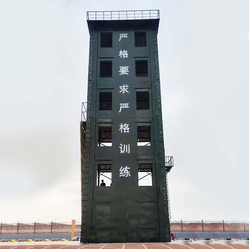
14 Heat Recovery Boiler Chimney Stack Platform Installation

15 Heat Recovery Boiler Platform Pipe Support Installation

16 STG Building Steel Structure Installation

17 Cable Tray Installation

18 Boiler Mechnical Parts Lifting Installation

19 Steam Turbine Generator Shaft Installation

20 Steam Turbine Blade Generator Installation

21 Prefabricated Electrical Substation Control Rooms Installation

22 Prefabricated Electrical Substation Containers 3 Levels

23 Elevated Boiler Flue Gas Duct Tee Diverter

24 Boilers STG Building at Glance

25 Electrical Cable Trays Installation

26 Boiler HRSG System Construction Ongoing

27 Conbined Cycle Power Plant Layout

28 HRSG Boiler Top Protection Canopy Roof Sheds

29 STG System Erection

30 Boiler System Piping Instrument Installation

31 Drone View Layout Wassa Site

32 Chirano Plant Gas Turbine Exhaust Duct Heat Recovery Facilities

32 Edikan Power Plant Boiler Installation

33 Boiler Deaerator System Installation

34 STG Building Overcrossing Bridge Pipe Rack Cable Tray Installation

34 STG Building Overhead Crane 32ton Installation

35 DCS Substation Control Rooms Prefabricated Multiple Floors

36 Multiple Floor Elevated Pipe Support Rack Structures

37 20m High Boiler Canopy Sheds Roof Cladding Panels Installation
Why ZHM Huawu Metal Gas Turbine Combined Cycle Waste Heat Recovery (WHR) Power Plants ?
 |
 |
 |
 |
| Reliable and Customized Designs | Cutting Edge Designing Process | Free Online Price System | Easy Bolt-by-number Assembly |
 |
 |
 |
 |
| Over Two Decades of Experience | Value For Money | Unmatched in Quality and Craftmanship | Excellent Customer Service |
Would you like to see more information and images of ZHM Huawu Steel's Metal Gas Turbine Combined Cycle Waste Heat Recovery (WHR) Power Plants ? Visit our Photo Gallery.
HOW CAN WE HELP YOU?
ZHM’s world-class team — together with our raw material suppliers and subcontractors — works to solve your most challenging design, engineering, farbrication or construction issues.
Contact ZHM by telephone at +86 135-8815-1981 (wechat and whatsapp) or send us your questions via email to info@zhmsteelworks.com